How to install indoor LED display
780 views admin 2023-09-14
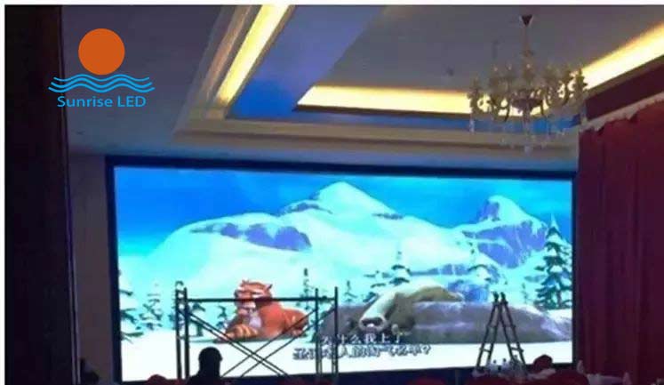
- Installation of indoor LED display, the commonly used method will choose to buy borders, modules, wiring, power, control card and other materials to assemble into their own LED display, then how to assemble a block of modules into a large LED screen, and normal use? Small series for you to explain the magnetic strip screen installation steps.
- First calculate the size: the unit board uses P5 full-color module size of 320*160mm, 15 pieces long, 12 pieces high, this color screen share 180 modules. 320*15=4800mm, 160*12=1920mm, the net area is 4800mm*1920mm plus 10mm of the remaining head (excluding the stainless steel package with 2mm, the final plate and the joint of the border is 5-8mm. The rest of the top and bottom can be left to the top from the front to see), the size of the border is 4810mm*1930mm.
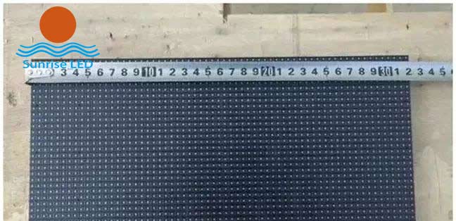
- P5 interior die group size 320mm
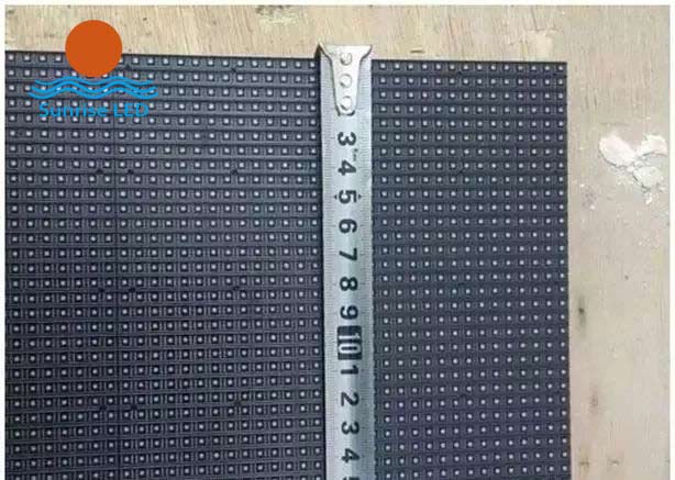
- P5 interior module width 160mm
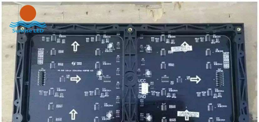
- P5 interior module back
- First, do the border
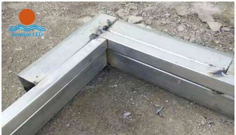
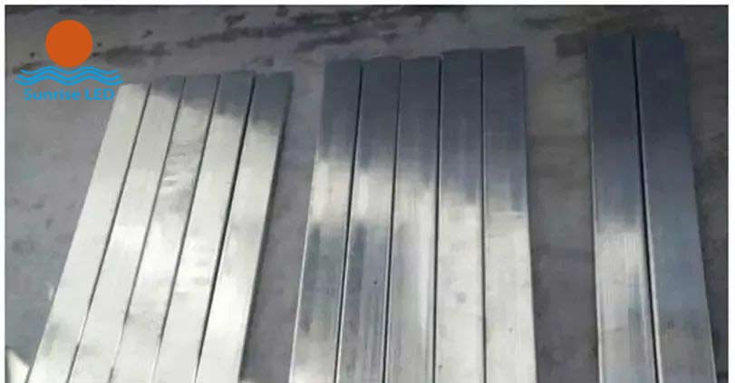
- Make a structure based on an existing example of a small screen being made. Buy 4*4 square steel from the market 4 2*2 4 (6 meters long), first use 4*4 square steel to make a field frame (can be customized according to their own situation), the size of the large border is 4850mm*1970mm, because the size of the small border is the size of the screen, the square steel is 40mm, so it is this size. When welding, use a steel square to weld as close as possible to 90 degrees. The size in the middle doesn't matter. After the frame is done, the small square steel is welded on the top, and the internal size of the small square steel is 4810mm*1930mm. The four corners and the middle are cut into small sections with the remaining 4*4 square steel.

- 4*4 and 2*2 square steel
- Square pass welding
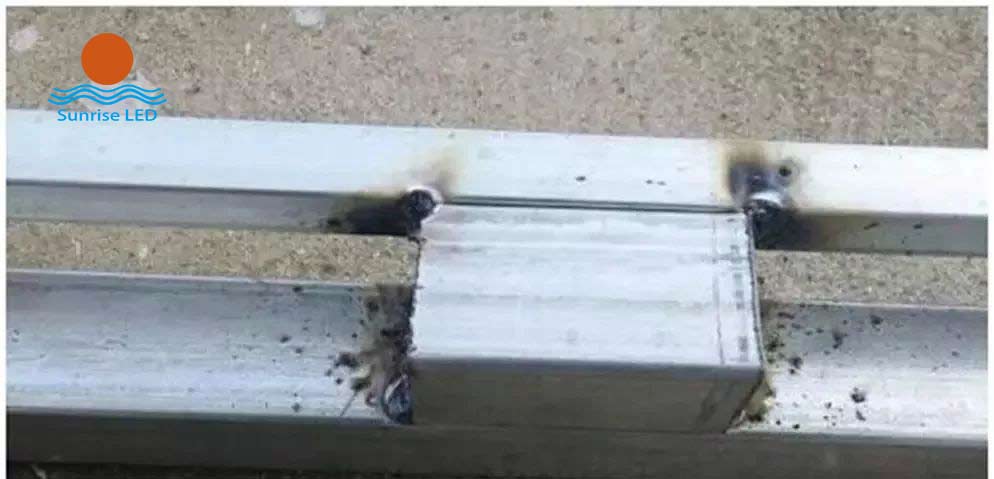
- Square pass welding 1
-
- Square pass welding 2
- Square pass welding 3
- Square pass welding 4
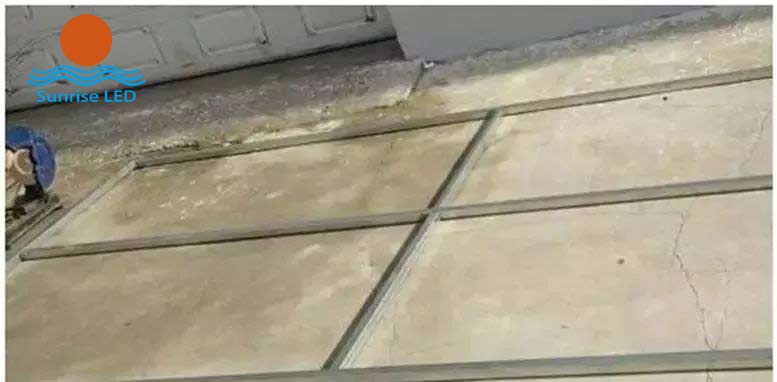
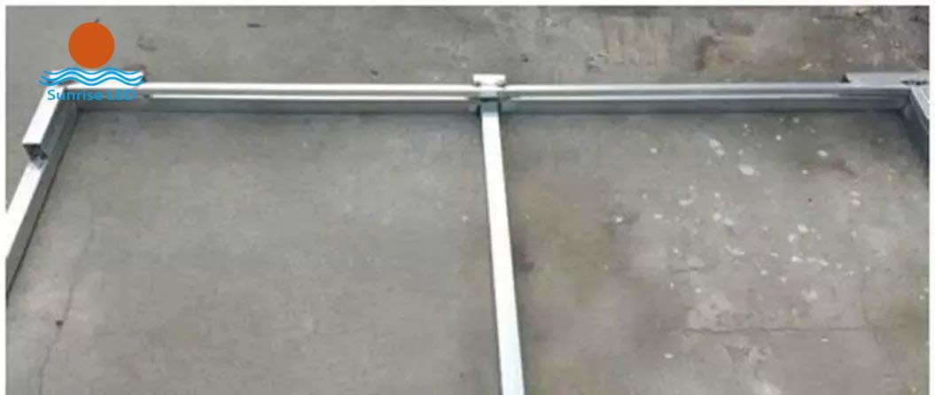
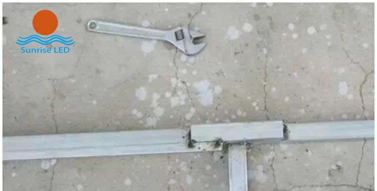
- After the small frame is done, begin to weld the back strip, and measure the first two pieces with the plate welding, and then weld down after finding the size. The back strip is 40mm wide, the length is about 1980mm, and the two ends can be welded well. The welded frame (the picture is the back) can be taken to the hall for installation. Make two Angle hooks at the top of the wall.
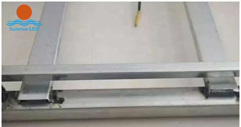
Weld back strip
Square steel back bar
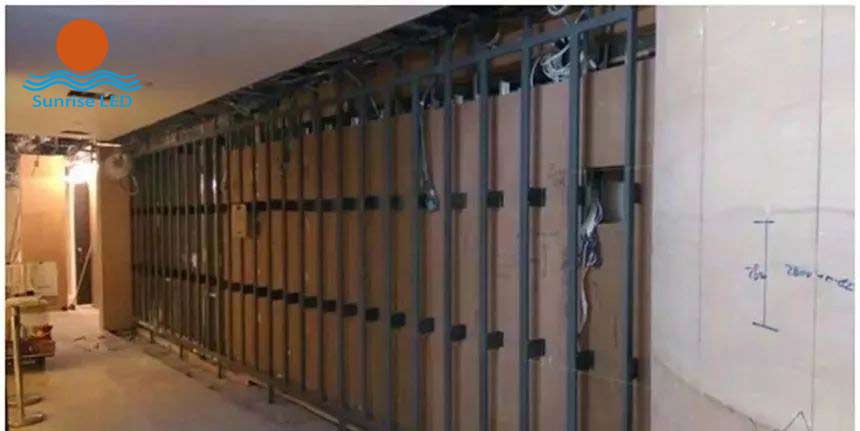
- Fasten the welded square steel to the wall
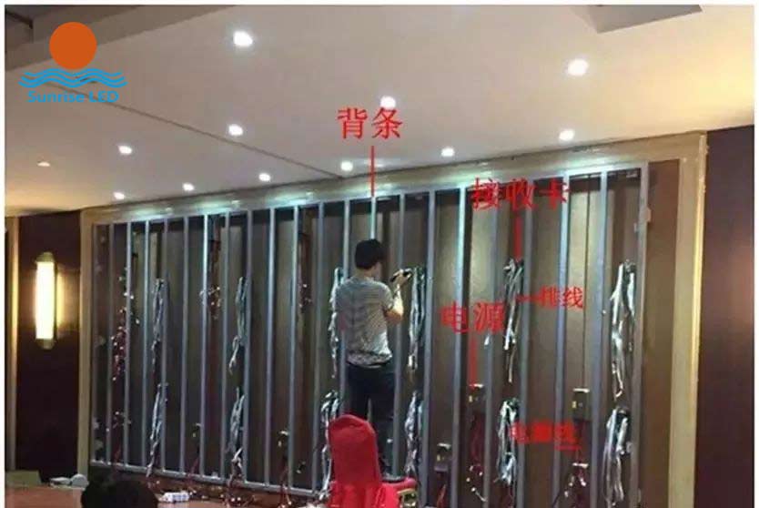
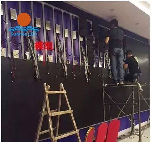
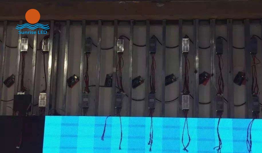
- Second, install power supply, control card, module
- After the shelf is hung, leave about 10mm gap around, because the indoor screen can not be made into a box frame with a fan, only by this 10mm gap simple ventilation.
- When installing the power supply, first connect the two finished power lines, 5V output must be positive and negative, otherwise burn the power line, module and control card.
- Each finished power cord has two connectors so that each power supply can carry four modules. Then the power supply is 220V connection, use 2.5 square soft copper wire to string each row together on the line, and finally out a group of 220V power cables, connected to the switchboard terminal. The cable from the distribution room to the LED display distribution cabinet must be arranged before the installation of the screen, and the cable diameter calculation has been discussed in the previous article, and it is no longer repeated here. After the power supply is connected, install the control card, and the control card is used here to receive the synchronous card. The layout of the entire power supply and control card, the LED display factory is a "power supply and system wiring diagram", as long as the drawing is strictly followed, there will be no mistake. General engineers themselves can also estimate the off-line mode according to the number of power supplies and cards.
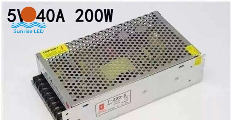
LED display power supply 5V 40A
- Secure the power supply to the position of the strip
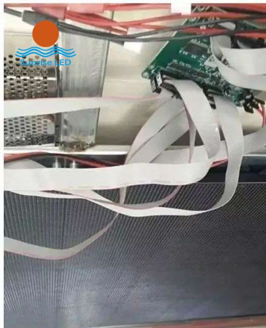
- Third, the receiving card is connected with the module
- We here each card with three columns of modules, a total of 36 boards, so each three columns install a card, from the nearest power supply 5V to the card power, pay attention to the positive and negative poles, and then use network cables to connect 5 cards, by the power connector of the network port is the input port, the right is the first card, is also the head card, the input is connected to the computer's gigabit network card, Then the output port is connected to the input port of the second card, and the output port of the second card is connected to the input port of the third card, so that all the way to the last card, the fifth card, the input is connected to the output of the fourth card. The output outlet is empty.
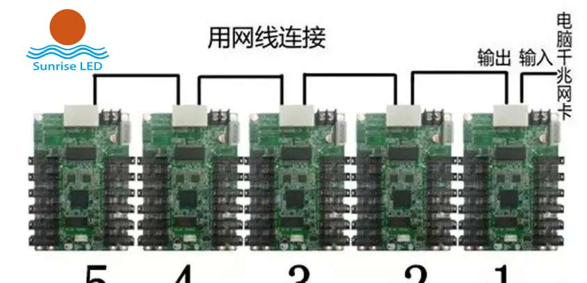
- Network cable diagram of the receiving card
- Before installing the module to use stainless steel wrapping, this is just to look good, but also the installation unit requirements, specially found the master to do stainless steel to measure the size, I estimated that he increased the 5mm after measuring the steel structure, in order to facilitate the installation and can stick the stainless steel wrapping. Here because the screen size is not large, we install the stainless steel wrap in advance, and sometimes you can install the stainless steel wrap after the screen is installed, but it should be noted that the bottom of the first row of horizontal must be done.
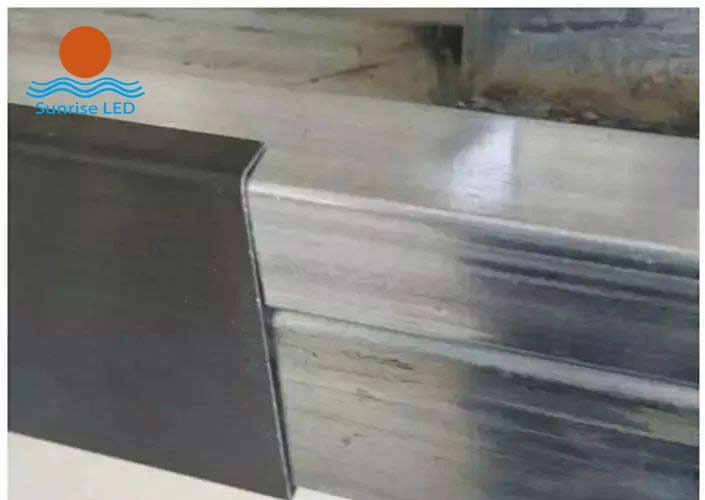
LED module stainless steel edge
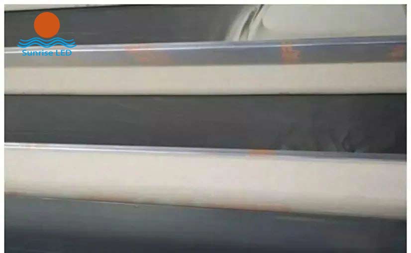
- LED module stainless steel edge 1
- Fourth, install the module
- After the stainless steel edge is fastened, it can be opened and applied to the module. Modules are generally mounted from the bottom, starting from the middle to the sides. There are many controversies in this way of installation, I explain our idea, from the bottom installation is mainly to make horizontal and vertical can be in the normal control range, especially after the screen area is large, it is easier to get out of control, especially the small spacing requirements are too high, a little gap does not meet the requirements, all need to make fine adjustments. Engineers who install too small spacing know that even if the precision mold comes out of the module or the box, there are still errors, and a few silk dislocation will lead to the dislocation of the whole line. Secondly, the installation from the middle to both sides can be divided into two groups of personnel or even four groups of personnel to work separately, saving installation time. Even if the problem of installation dislocation is encountered, it will not affect the progress of another group of personnel.
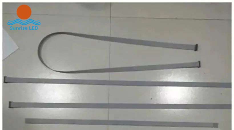
- The short line is only suitable for the connection between the module and the module. The long line from the control card to the module is to install the length of the line sequence. The top and bottom line are the longest, which is about 1 and a half meters long.
Install the LED module on the square steel
LED module length and wiring
- LED module 16P row cable
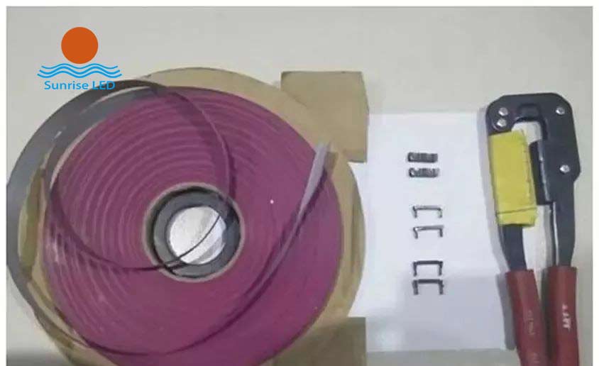
- It is best to have your own tools, if the line is crushed, re-cut a section, a pressure on both ends, and then install a fixed clip. Many times, because the back strip supports the uneven module, the cable card has to be cut off when installing. The red edge is pointing up when the cable is inserted into the module, and the arrow of the module is pointing up at the same time. If there is no marked arrow in the module, then the printing on the module must be upward. All connections between modules are made by connecting the input in front of the module to the output behind the previous module.
- This color screen shares 5 receiving cards, 1 card drags three columns of modules, each card has 12 T75 interfaces, this screen is also 12 rows from top to bottom, just plug in, the corresponding plug can be. The bottom pin of the screen interface is marked OE, but it is not the red edge of the strip line, (this is the opposite of the single and double color screen), and the strip line will not burn the module or card, but a bright line will be displayed on the module.
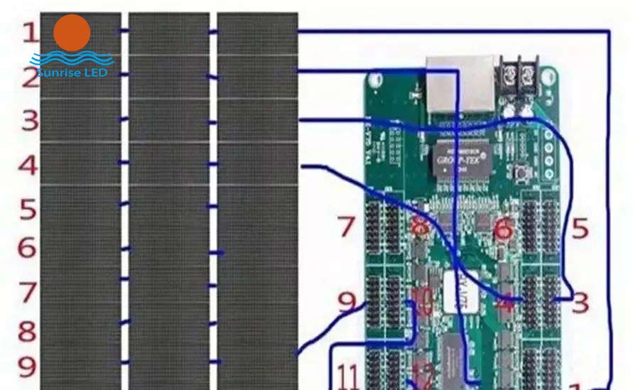
Receiving card and module wiring diagram
- Receiving card and module wiring diagram
- 5. Debugging
- Install a four-line module a card after the power test, if there is a problem, it will be solved in time, because then install a group of words will cover the card can not be tested, in addition to continue to install the problem can not be found in time, if all are installed, and then go to find the problem point, and remove the installed module, the amount of engineering can be much larger. There is a test button on the control card, just powered on, you can first use this way to test, if the installation is normal, the screen will display red, green, blue, line, field, point information, and then the control computer test again, mainly to test whether the network cable communication is normal. If normal, then install the next group until the installation is complete.
Test whether some installed modules display properly
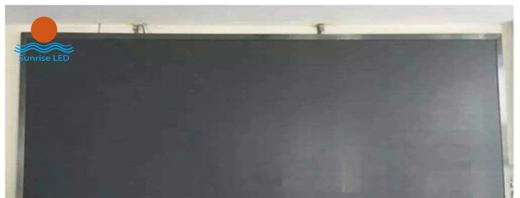
Install all modules and wrap edges