3 views admin 2026-03-13
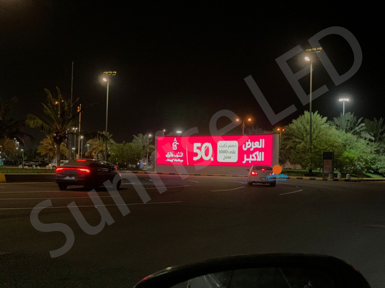
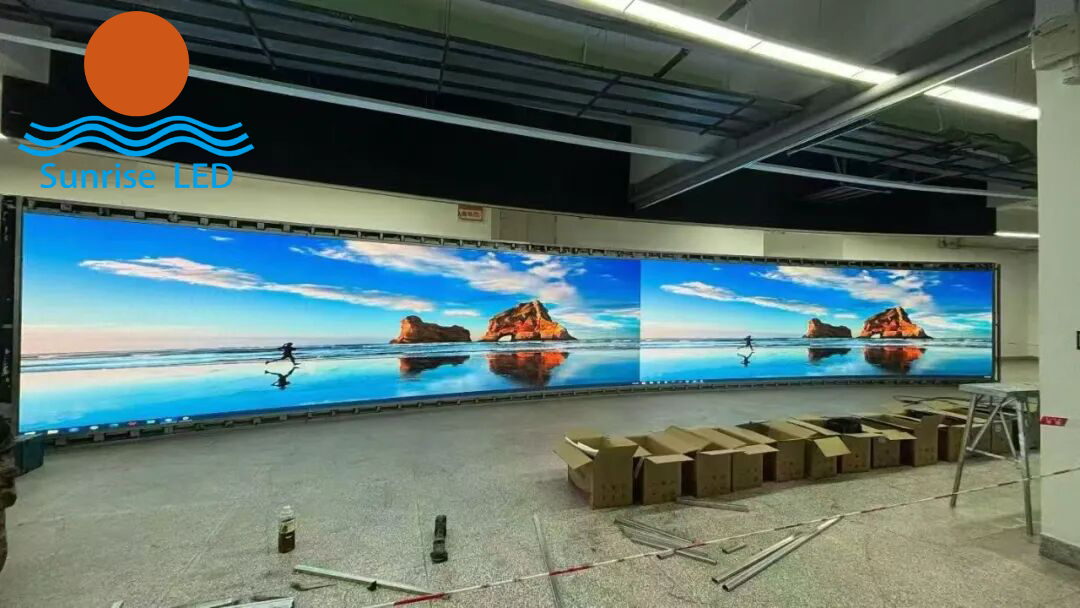 For friends working on LED screen projects, this problem is all too common:After splicing a large screen, obvious bright lines, dark lines, or even a “split-face” effect often appear between modules.Even if you carefully adjust the physical gaps to ensure perfect alignment during installation, the bright and dark lines still remain.This not only ruins the overall display quality but also causes delays in customer acceptance, with endless debugging yielding little effect.
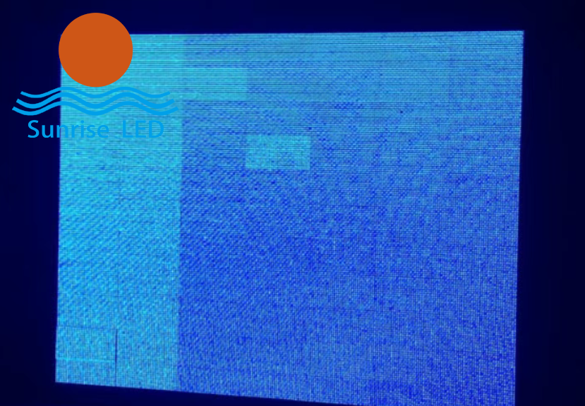
First, avoid this mistake:Bright/dark lines ≠ installation misalignmentThere are 3 real main causes:
Differences in brightness and chroma between modules themselves
Natural brightness attenuation at splicing edges
Incorrect calibration parameter settings
With the right calibration method, you don’t need to blindly adjust physical gaps.You can easily fix the issue using the receiver card software and pass customer acceptance efficiently.
For friends working on LED screen projects, this problem is all too common:After splicing a large screen, obvious bright lines, dark lines, or even a “split-face” effect often appear between modules.Even if you carefully adjust the physical gaps to ensure perfect alignment during installation, the bright and dark lines still remain.This not only ruins the overall display quality but also causes delays in customer acceptance, with endless debugging yielding little effect.
First, avoid this mistake:Bright/dark lines ≠ installation misalignmentThere are 3 real main causes:
Differences in brightness and chroma between modules themselves
Natural brightness attenuation at splicing edges
Incorrect calibration parameter settings
With the right calibration method, you don’t need to blindly adjust physical gaps.You can easily fix the issue using the receiver card software and pass customer acceptance efficiently.
 Preparation: 2 key steps to avoid wasted effort
Proper preparation is critical to avoid useless calibration — a step many people overlook.
Check the screen’s basic conditionEnsure all modules are spliced flat, with no looseness or warping.Cables must be securely connected to rule out bright/dark lines caused by poor hardware contact.
Verify parameters in the receiver card softwareConfirm module model, pixel pitch, and scanning method are fully consistent.Eliminate display abnormalities caused by mismatched parameters.
Preparation: 2 key steps to avoid wasted effort
Proper preparation is critical to avoid useless calibration — a step many people overlook.
Check the screen’s basic conditionEnsure all modules are spliced flat, with no looseness or warping.Cables must be securely connected to rule out bright/dark lines caused by poor hardware contact.
Verify parameters in the receiver card softwareConfirm module model, pixel pitch, and scanning method are fully consistent.Eliminate display abnormalities caused by mismatched parameters.
 Only when the basics are done correctly will calibration be effective.
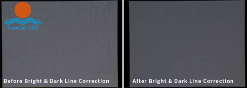
Core Operation: Bright & Dark Line Compensation
After preparation, we move to the core step:Bright and dark line compensation calibration — the most direct and effective solution, done entirely in the receiver card software.
Find the Bright/Dark Line Compensation function.
Click Auto Detect to let the software identify brightness differences at splicing edges and generate basic compensation parameters.
Important note:Do NOT directly use the software’s default parameters.Default settings cannot fit all screen types, and blind application will only backfire.
The correct way:Fine-tune parameters based on the actual on-site display:
For bright line areas: slightly reduce the edge brightness of the corresponding module
For dark line areas: slightly increase the edge brightness
Only when the basics are done correctly will calibration be effective.
Core Operation: Bright & Dark Line Compensation
After preparation, we move to the core step:Bright and dark line compensation calibration — the most direct and effective solution, done entirely in the receiver card software.
Find the Bright/Dark Line Compensation function.
Click Auto Detect to let the software identify brightness differences at splicing edges and generate basic compensation parameters.
Important note:Do NOT directly use the software’s default parameters.Default settings cannot fit all screen types, and blind application will only backfire.
The correct way:Fine-tune parameters based on the actual on-site display:
For bright line areas: slightly reduce the edge brightness of the corresponding module
For dark line areas: slightly increase the edge brightness
 Adjust by 5%–10% each time
Compare with adjacent modules repeatedly to avoid over-adjustment, which creates new color differences.
Advanced Optimization: Uniformity Calibration
If bright/dark lines are accompanied by obvious color differences, compensation alone is not enough.Add this third step: Brightness & Chroma Uniformity Calibration.
In the control software, open the Pixel-by-Pixel Calibration function.You don’t need to calibrate the entire screen —focus only on the splicing area modules, adjusting edge pixel brightness and chroma to unify the display effect and completely eliminate the “split-face” effect.
After calibration:
Save parameters
Restart the screen
Double-check that bright and dark lines are completely gone
Critical Reminders: 2 common mistakes to avoid
These are the top reasons calibration fails for many technicians:
Keep ambient light evenAvoid strong direct light on the screen during calibration.Bright light interferes with detection accuracy and distorts parameters.
Old screens: replace aged modules firstIf bright/dark lines appear on an old screen, they are usually caused by LED aging and attenuation.Do NOT calibrate immediately —replace severely degraded modules first, then calibrate.Otherwise, the effect will fade quickly and your work will be wasted.
Summary
LED screen bright/dark line calibration is actually simple and requires no complex professional equipment.Just follow the complete workflow:Preparation → Bright/Dark Line Compensation → Uniformity Calibration
This will solve the problem efficiently, save debugging time, and greatly improve your customer acceptance rate.
Adjust by 5%–10% each time
Compare with adjacent modules repeatedly to avoid over-adjustment, which creates new color differences.
Advanced Optimization: Uniformity Calibration
If bright/dark lines are accompanied by obvious color differences, compensation alone is not enough.Add this third step: Brightness & Chroma Uniformity Calibration.
In the control software, open the Pixel-by-Pixel Calibration function.You don’t need to calibrate the entire screen —focus only on the splicing area modules, adjusting edge pixel brightness and chroma to unify the display effect and completely eliminate the “split-face” effect.
After calibration:
Save parameters
Restart the screen
Double-check that bright and dark lines are completely gone
Critical Reminders: 2 common mistakes to avoid
These are the top reasons calibration fails for many technicians:
Keep ambient light evenAvoid strong direct light on the screen during calibration.Bright light interferes with detection accuracy and distorts parameters.
Old screens: replace aged modules firstIf bright/dark lines appear on an old screen, they are usually caused by LED aging and attenuation.Do NOT calibrate immediately —replace severely degraded modules first, then calibrate.Otherwise, the effect will fade quickly and your work will be wasted.
Summary
LED screen bright/dark line calibration is actually simple and requires no complex professional equipment.Just follow the complete workflow:Preparation → Bright/Dark Line Compensation → Uniformity Calibration
This will solve the problem efficiently, save debugging time, and greatly improve your customer acceptance rate.
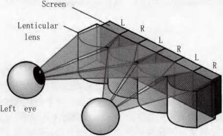
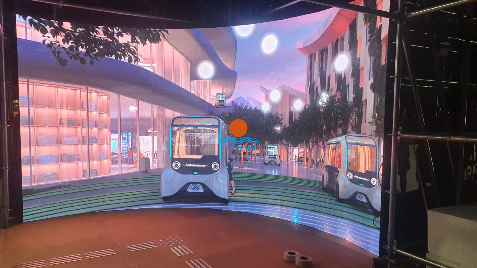
At present, the naked eye 3D large screen market is hot, and 3D technology is also known as 3D di...
Sunrise’s p2.604 curved LED display lights up under the Eiffel Tower Sunri...
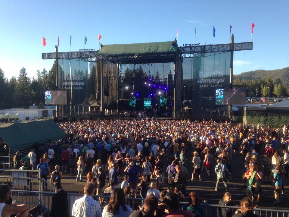
Concert activities are popular in the United States, and sunrise’s products have been wide...

Sunrise 264 square meters Galaxy 3115 series mesh led facade in Armenia Sun...

Doris, as a new salesman, won three orders in two months. It’s great. Jack, the bu...
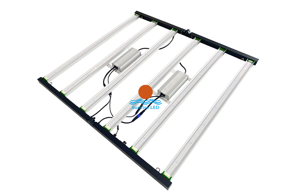
640w and 800W full spectrum led grow light It can be folded for convenient transportatio...

The latest project, Saudi Arabia LED MESH FACADE. Ultra-high brightness, ultra-light LED display ...